
Greetings to all gtrlife community
![Image]()
I'd like to join this forum and share some information about GTR road race project.
First of all please forgive me for my broken English - I will do my best but it may not be good enough anyway.
I'm coming from professional motorsport (worked with GTs, LMPs, Formula 3, GP2, touring cars etc.) where my main areas was chassis and suspension design, aerodynamics design, data analyses/setup work using simulation tools, on track engineering work (setup etc). Most of the time we where fabricating most of the stuff in house - suspension, composites etc. One day I became a bit tired (or better say my Wife did) of hectic schedule and too much politics involved in professional racing and I decided to open my own shop providing engineering expertise to pro teams and manufacturers but also oriented towards track enthusiasts - non professional racers. Target is to bring professional motorsport technologies and practices to enthusiast community.
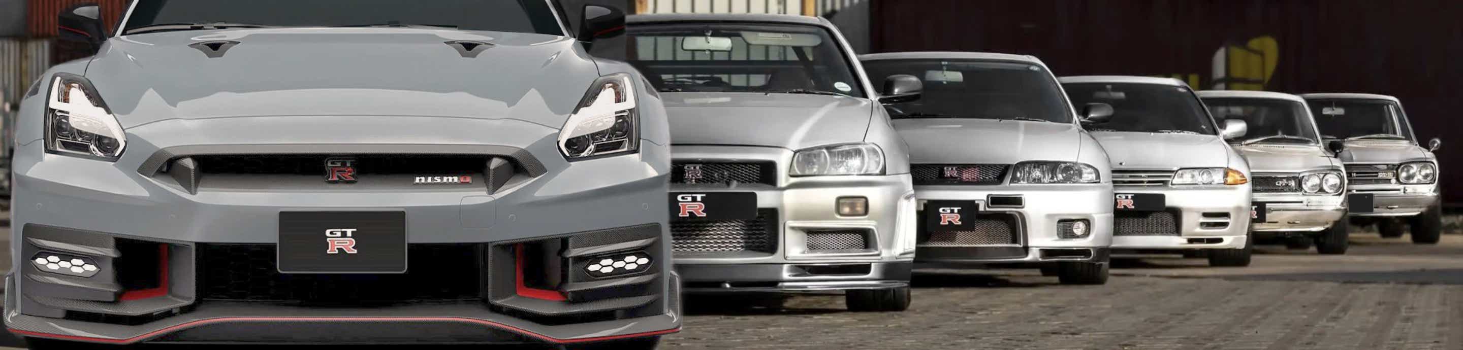
Zonda R was kind of inspiration in terms that it wasn't bound by strict technical regulations and guys could design and build it the way they like it. I also believe that if we make something that we really like the way we like it than there's a chance that someone might like it as well
![Image]()
My partner is GTR35 enthusiast and raced his car occasionally so we decided that we should build a full blown race car which would be used as development vehicle, showcase what we can do and give us tons of fun when we race it. The way we build it now - we decided to call it NGT-R (N referring to group N
![Image]()
) because for now we keep standard engine and gearbox as a base.
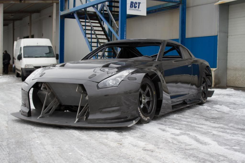
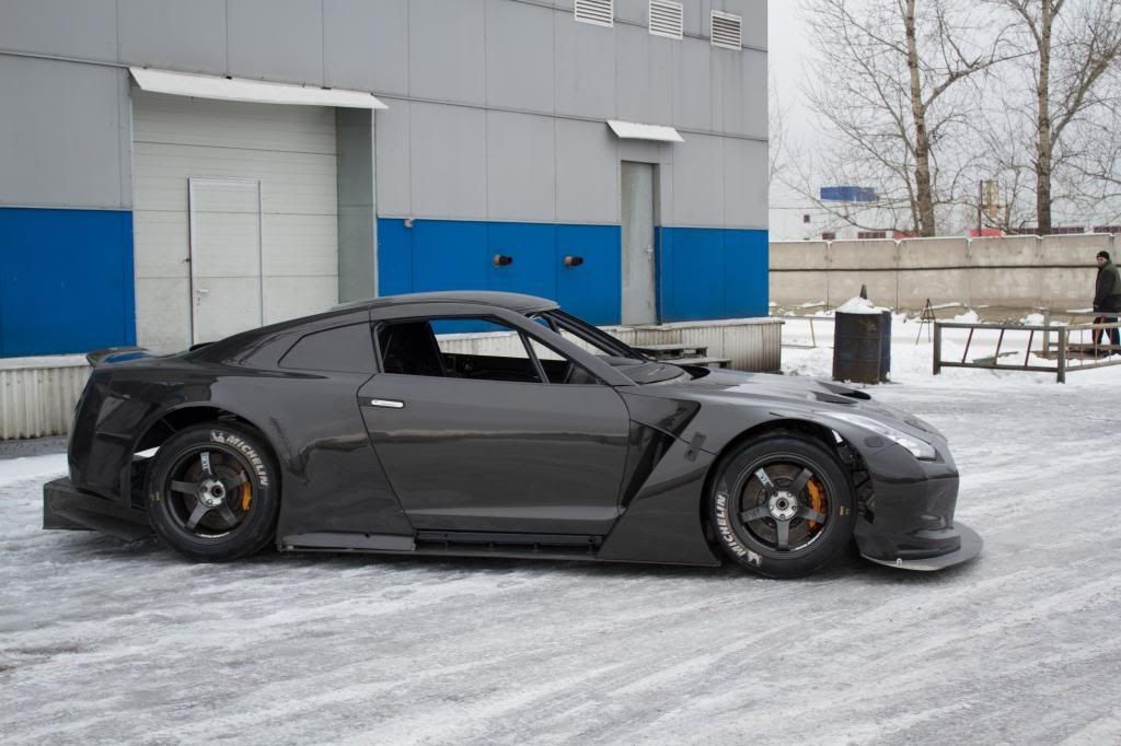
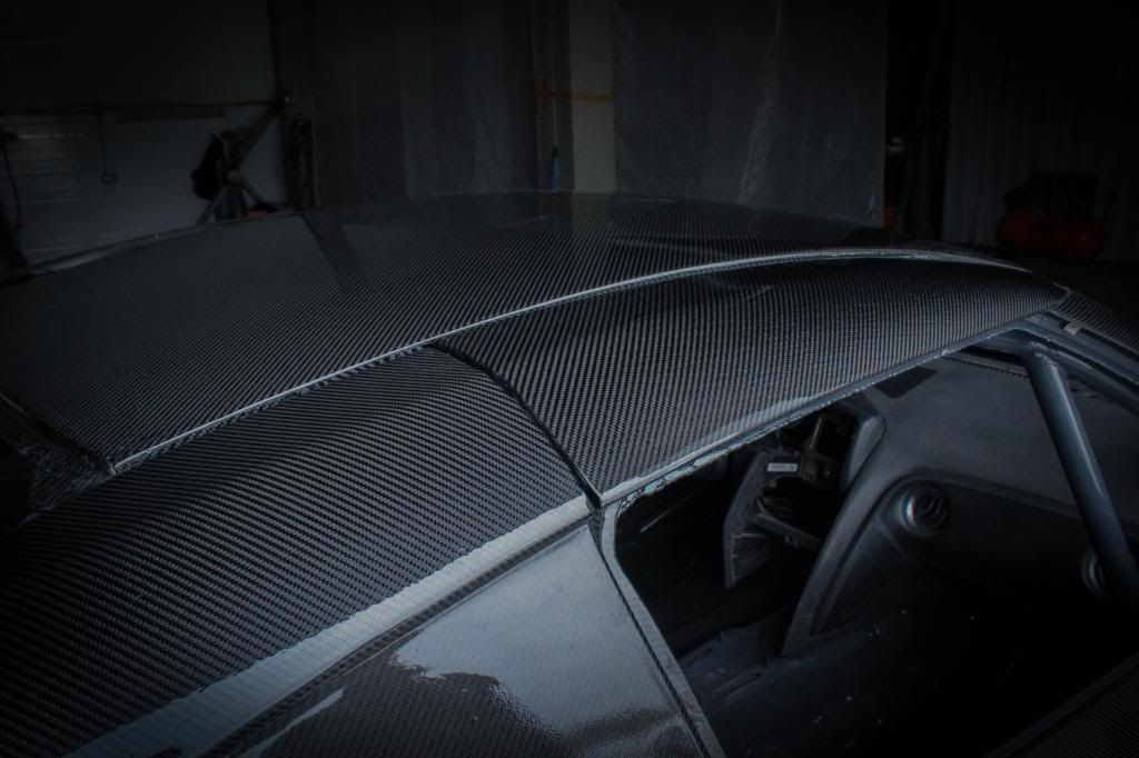
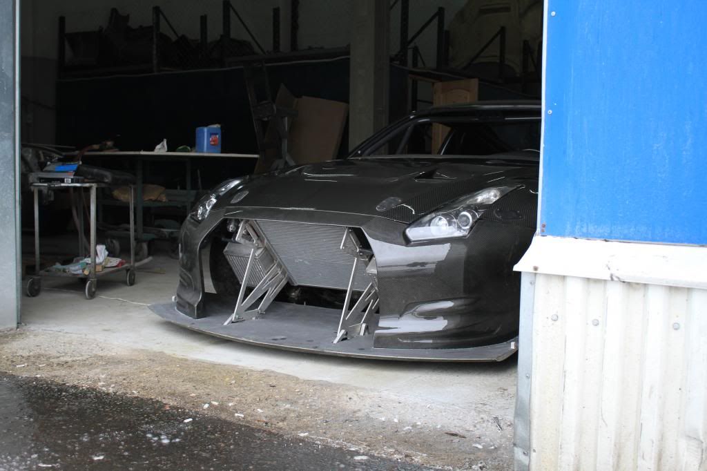
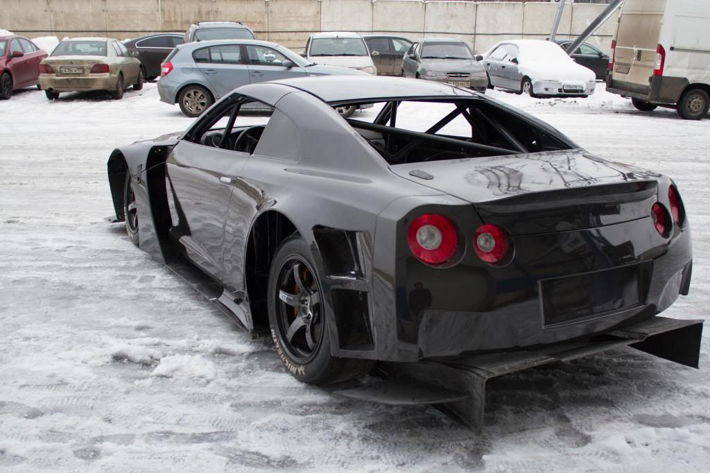
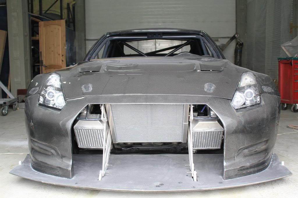
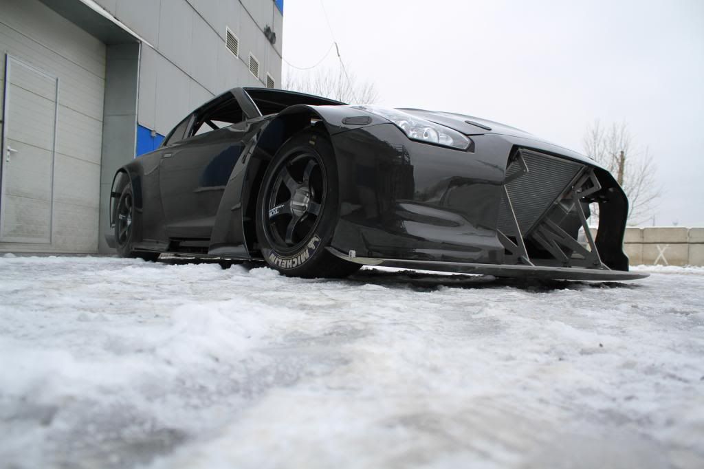
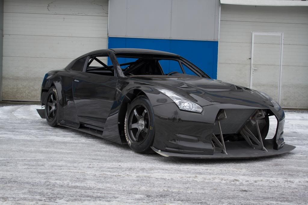
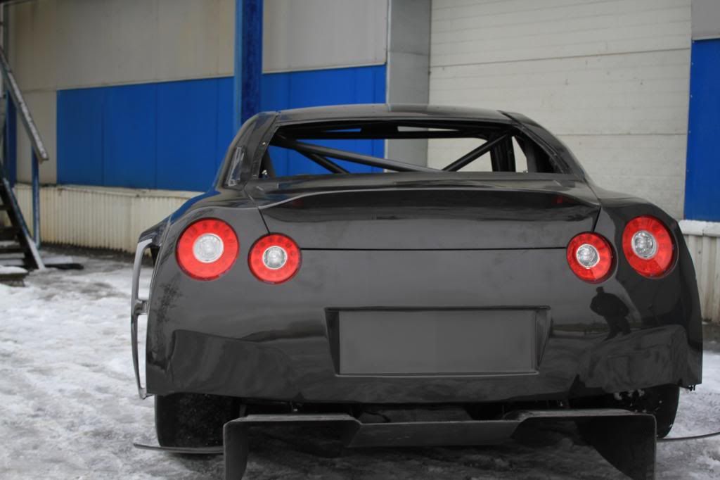
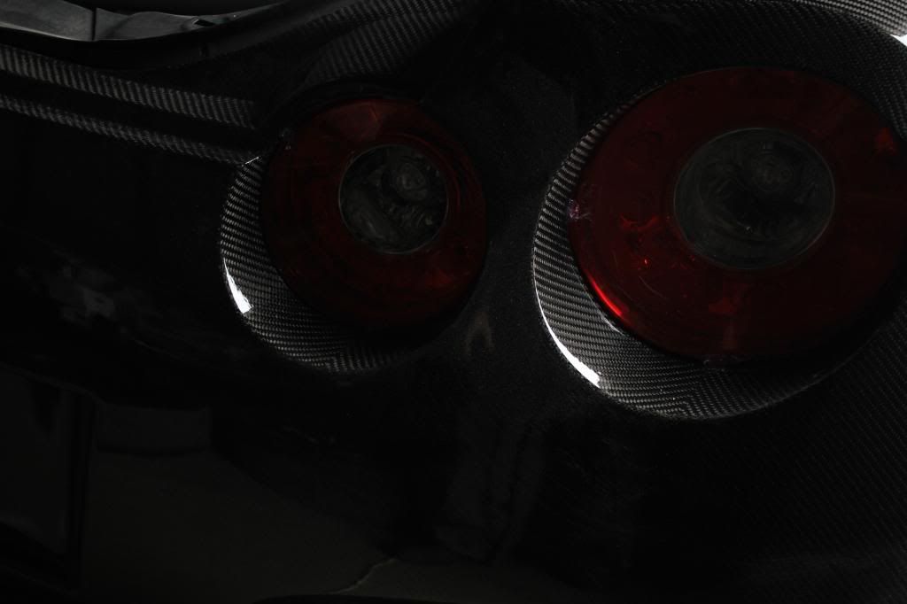
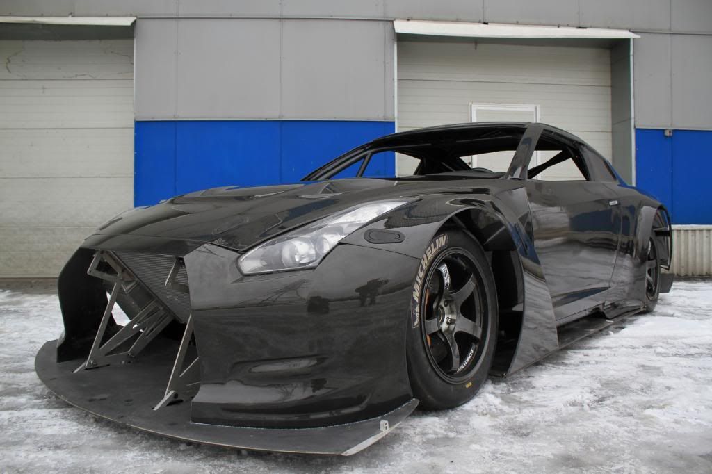
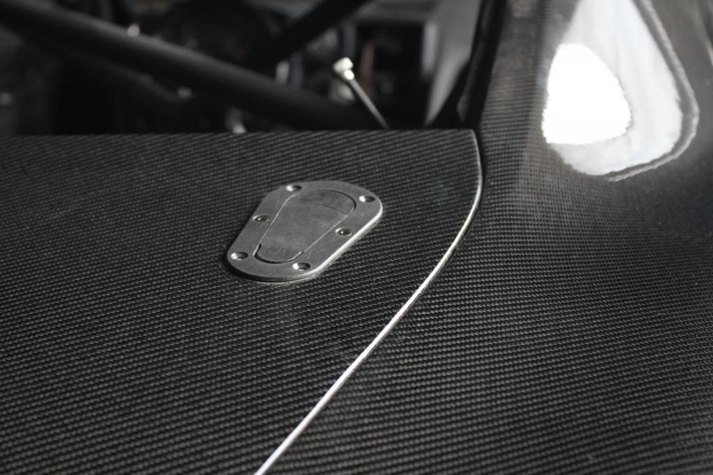
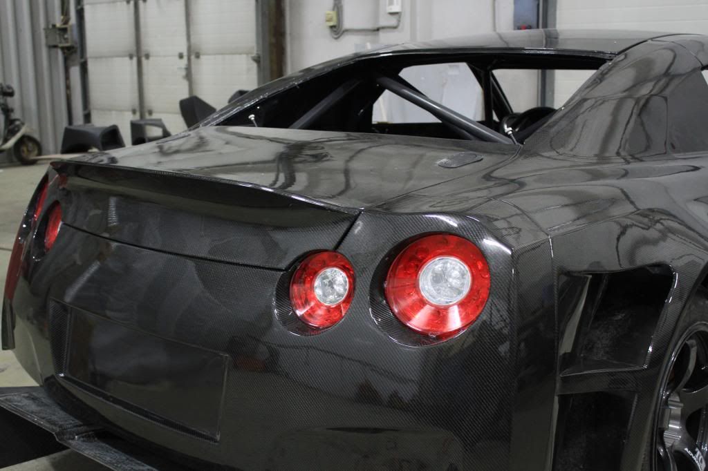
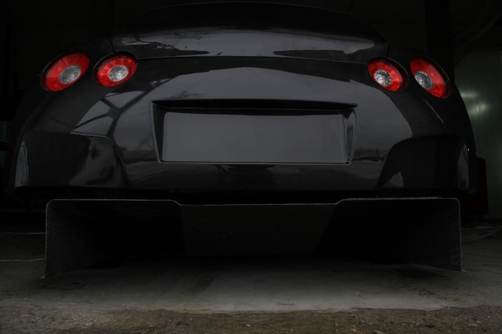
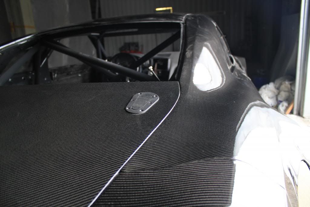
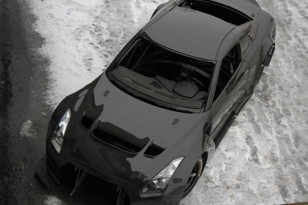
Project started at the end of September 2012 and about a couple of weeks ago we trial fitted carbon fiber bodywork. In order to adjust the gaps etc. Before we started to do that I could not resist to take some pictures. Please, keep in mind that this is not finished product - many parts are missing (but coming along nicely) like: two element high downforce rear wing (with measured Cl/Cd performance), grill and front ducting (ducts from bumper to radiator, intercoolers, brakes and from radiator/intercoolers to engine hood), side seals, mirros, etc. Car is standing on narrow 28/71-28 michelins on 11" wheels while it is designed for 31/71-18 (same as nismo/jrm used in FIA GT1 and now GT3 programm) on 13" wheels. So it looks funny and wrong but tires should be here fairly soon. Parts between rear bumper corners are missing and rear diffuser would be trimmed to it's final shape. It (diffuser) is also missing vertical strakes and vortex generators. I guess that because snow reflecting too much light or because of my non existent photographing skills it's not really visible that antire bodywork is clear coated (ultraviolet protection) carbon fiber... But in the flash it's visible very well
![Image]()
In fallowing posts I will share ideas/purpose behind various elements/solutions and go through some aspects of design/build process but for now I'm happy to share how it looked like (work in pprogress) during trial body fit
Thanks
Ted

I'd like to join this forum and share some information about GTR road race project.
First of all please forgive me for my broken English - I will do my best but it may not be good enough anyway.
I'm coming from professional motorsport (worked with GTs, LMPs, Formula 3, GP2, touring cars etc.) where my main areas was chassis and suspension design, aerodynamics design, data analyses/setup work using simulation tools, on track engineering work (setup etc). Most of the time we where fabricating most of the stuff in house - suspension, composites etc. One day I became a bit tired (or better say my Wife did) of hectic schedule and too much politics involved in professional racing and I decided to open my own shop providing engineering expertise to pro teams and manufacturers but also oriented towards track enthusiasts - non professional racers. Target is to bring professional motorsport technologies and practices to enthusiast community.
Zonda R was kind of inspiration in terms that it wasn't bound by strict technical regulations and guys could design and build it the way they like it. I also believe that if we make something that we really like the way we like it than there's a chance that someone might like it as well
My partner is GTR35 enthusiast and raced his car occasionally so we decided that we should build a full blown race car which would be used as development vehicle, showcase what we can do and give us tons of fun when we race it. The way we build it now - we decided to call it NGT-R (N referring to group N

Project started at the end of September 2012 and about a couple of weeks ago we trial fitted carbon fiber bodywork. In order to adjust the gaps etc. Before we started to do that I could not resist to take some pictures. Please, keep in mind that this is not finished product - many parts are missing (but coming along nicely) like: two element high downforce rear wing (with measured Cl/Cd performance), grill and front ducting (ducts from bumper to radiator, intercoolers, brakes and from radiator/intercoolers to engine hood), side seals, mirros, etc. Car is standing on narrow 28/71-28 michelins on 11" wheels while it is designed for 31/71-18 (same as nismo/jrm used in FIA GT1 and now GT3 programm) on 13" wheels. So it looks funny and wrong but tires should be here fairly soon. Parts between rear bumper corners are missing and rear diffuser would be trimmed to it's final shape. It (diffuser) is also missing vertical strakes and vortex generators. I guess that because snow reflecting too much light or because of my non existent photographing skills it's not really visible that antire bodywork is clear coated (ultraviolet protection) carbon fiber... But in the flash it's visible very well
In fallowing posts I will share ideas/purpose behind various elements/solutions and go through some aspects of design/build process but for now I'm happy to share how it looked like (work in pprogress) during trial body fit


Thanks
Ted